Self-aspirated Flotation Cell
Working Principle
Flotation machine is named as flotation cell and froth flotation concentrator.
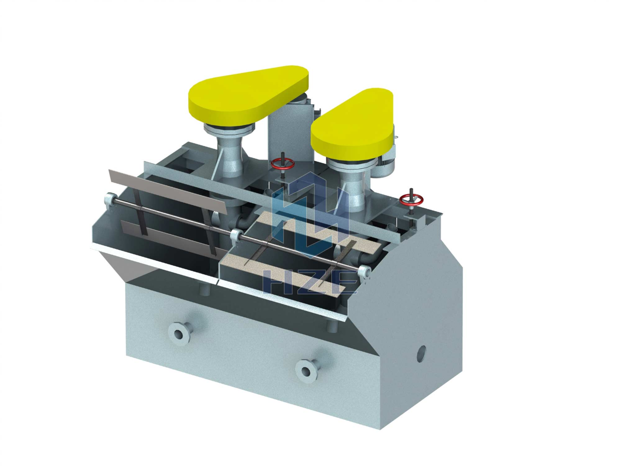
When the impeller rotates, slurry in upper and lower impeller chambers is pushed all around by the centrifugal force produced by the action of upper and lower vanes, forming a negatives pressure. Meanwhile, the slurry on the cover plate is sucked into the upper impeller chamber through the circular hole, forming up the circulation of slurry. When the ore slurry is thrown around by the lower vane, the ore slurry under lower vane flows to the center to complement, forming the down circulation of slurry. Air sucked into the upper impeller chamber and mixes with the sucked slurry through suction pipe and center cylinder, a large amount of air bubbles are formed. After steady flow through the cover board, these bubbles are evenly dispersed in the cell, forming mineral froth. Then mineral froth will rise to the foam layer and become foam production by the scraper.
Features
The impeller with backward-style two-sided vanes ensures double circulation of ore slurry in the cell.
The large interval between the impeller and cover plate ensures a large amount of air suction.
Special Tips
Mechanical stirring, automatic air and ore slurry suction.
It can be combined with other type flotation cells to be a set of flotation cells as suction cells of each operation.
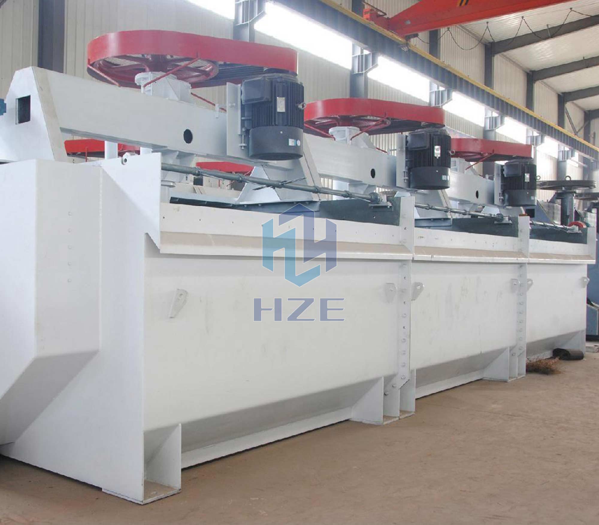
Application Scope
Flotation cell is one of the most commonly used mining equipment, which is widely used in mineral processing and chemical industries. In the production of small scale, medium scale or large scale mineral processing Plants, it is generally used as the concentration machine to recover metal minerals of gold, silver, copper, lead, zinc, nickel, manganese, iron, molybdenum, tungsten and others, as well as barite, quartz, graphite, feldspar, fluorspar, etc.
Technical Parameters
|
Model |
Effective Volume (m3) |
Capacity (m3/min) |
Impeller Diameter (mm) |
Impeller Speed (r.p.m) |
Agitator Power (kW) |
Paddle Power (kW) |
|
SF-0.37 |
0.37 |
0.2-0.4 |
300 |
352-442 |
1.5 |
0.55 |
|
SF-0.7 |
0.7 |
0.3-1.0 |
350 |
336 |
3 |
1.1 |
|
SF-1.2 |
1.2 |
0.6-1.2 |
450 |
312 |
5.5 |
1.1 |
|
SF-2 |
2 |
1.5~3 |
550 |
280 |
11 |
1.5 |
|
SF-2.8 |
2.8 |
1.5-3.5 |
550 |
280 |
11 |
1.5 |
|
SF-4 |
4 |
2.0-4 |
650 |
235 |
15 |
1.5 |
|
SF-6 |
6 |
3~6 |
760 |
191 |
30 |
2.2 |
|
SF-8 |
8 |
4.0-8 |
760 |
191 |
30 |
2.2 |
|
SF-16 |
16 |
5.0-16 |
850 |
169-193 |
45 |
1.5 |
|
SF-20 |
20 |
5.0-20 |
850 |
186 |
45 |
1.5 |
 DOWNLOAD


